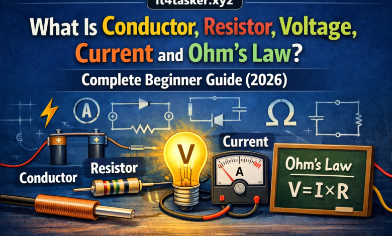
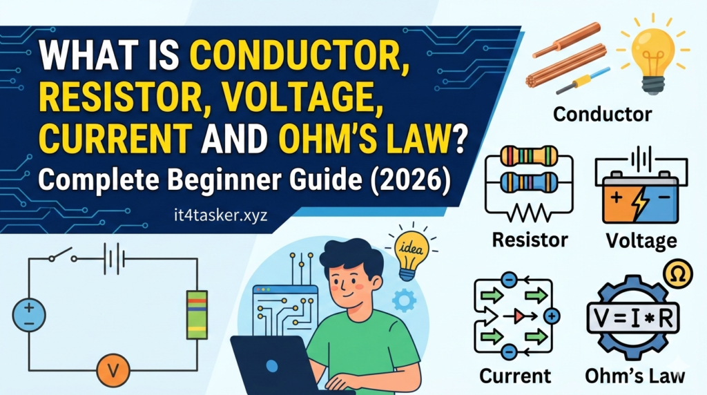
What Is Conductor, Resistor, Voltage, Current and Ohm’s Law? Complete Beginner Guide (2026):
Introduction:
Starting to learn about power can seem like a new language. But, knowing electrical basics is key to understanding how devices work every day. It helps you understand every switch in your home.
Ever wondered how energy moves through wires or why some materials stop it? This guide breaks down these complex ideas into simple steps. It makes hard concepts easy for anyone looking to learn more.

We’ll look at how pressure pushes energy through your home’s circuits. We’ll also dive into the math that connects all parts logically.
When you understand Ohm’s Law explained, everything becomes clear. This journey to knowledge begins here.
Key Takeaways
- Understand materials that permit energy flow easily.
- Identify parts that limit the speed of power.
- Grasp the force driving energy through a circuit.
- See how various units interact with each other.
- Learn to analyze simple power paths effectively.
- Build a strong foundation for future learning.
Understanding the Basics of Electricity
Electronics start with the basics of electricity. Electricity powers our devices, machines, and homes. It’s key to modern life, and knowing it is important for electronics fans.
Electricity is about electrons moving in wires. This movement is called electric current. Voltage, or electrical pressure, pushes these electrons along.
Key Components of Electricity
| Component | Description |
|---|---|
| Electric Current | The flow of electrons through a conductor |
| Voltage | The electrical pressure driving the current |
| Resistance | The opposition to the flow of electric current |

Electricity comes from changing energy types into electrical energy. This energy travels through power lines to our places. There, it powers many devices.
Studying electricity means learning how it acts and how to use it. We look at conductors, insulators, and more in circuits.
What Is a Conductor and How Does It Work?
Conductors are materials that let electricity flow through them easily. They are very important. A conductor is a substance that lets electric current flow freely. This makes them key in many areas, like home wiring and electronic devices.
The Science Behind Electrical Conductivity
Electrical conductivity is when a material can carry electric current. It depends on the material’s atomic structure and free electrons.
How Electrons Move Through Conductive Materials
In conductive materials, electrons can move freely. When a voltage is applied, these electrons gain energy and flow towards the positive terminal. This creates an electric current.
Atomic Structure and Free Electrons
The atomic structure of a material affects its conductivity. Materials with many free electrons, like metals, are good conductors. This is because these electrons can move freely within the material.

Common Types of Conductors in Everyday Life
Conductors are everywhere in our lives. Knowing how they work shows their importance.
Copper Wiring in Your Home
Copper is a common conductor because it conducts electricity well and is affordable. It’s used in home wiring and circuits.
Aluminum in Power Lines
Aluminum is used in power lines. It’s light and doesn’t corrode easily, making it great for overhead lines.
Gold and Silver in Electronics
Gold and silver are top conductors used in electronics and aerospace. They cost more but conduct better and don’t corrode.
| Conductor Material | Electrical Conductivity | Common Applications |
|---|---|---|
| Copper | High | Household wiring, electrical circuits |
| Aluminum | Medium to High | Power transmission lines |
| Gold | Very High | High-reliability electronics, aerospace |
| Silver | Very High | High-frequency applications, contacts |
Why Metals Make Excellent Conductors
Metals are great conductors because of their atomic structure. This structure allows for many free electrons. This makes metals good at carrying electrical current.
Understanding Insulators: The Opposite of Conductors
Insulators are key in keeping us safe from electrical shocks. They make sure electrical circuits work right. These materials block the flow of electric current.
Insulators stop electrons from moving freely. This is why they’re so important. They’re used in many places, like homes and big electrical systems.
How Insulators Protect and Control Electricity
Insulators keep us safe by covering conductors. This stops us from touching live wires by accident. They also help electricity flow where it should, making sure devices work right.
Key functions of insulators include:
- Preventing electrical shocks
- Protecting against short circuits
- Maintaining the integrity of electrical circuits
Real-World Examples of Insulators
Insulators are all around us. Here are some examples:
Rubber and Plastic Coverings
Rubber and plastic are great insulators. They’re used to cover wires and cables. This makes them safe to touch.
Glass and Ceramic Materials
Glass and ceramic are also good insulators. They’re used in high-voltage jobs and making electrical parts.
| Material | Insulation Property | Common Use |
|---|---|---|
| Rubber | High electrical resistance | Wire and cable coverings |
| Plastic | Good electrical insulation | Electrical wire insulation |
| Glass | Excellent insulation | High-voltage insulators |
| Ceramic | High insulation strength | Electrical components |
What Is a Resistor and Its Purpose?
Resistors are key in electronic circuits, controlling electrical current flow. They help regulate voltage, divide it, and end transmission lines. Knowing about resistors is vital for electronics work.
How Resistors Control Electrical Current
Resistors manage electrical current by offering resistance to electrons. This resistance is measured in ohms (Ω). The more resistance, the less current in the circuit.
Limiting Current Flow in Circuits
Resistors mainly limit current in circuits. By adding a resistor in series with a part, you stop too much current from harming it.
Protecting Sensitive Components
Resistors also safeguard sensitive parts from voltage spikes or too much current. For instance, LEDs are often paired with resistors to control current and avoid burnout.
Different Types of Resistors Explained
There are many types of resistors, each with special features and uses.
Fixed Resistors
Fixed resistors have a fixed resistance value and are the most used. They come in various power ratings and are used in many applications.
Variable Resistors and Potentiometers
Variable resistors, or potentiometers, offer adjustable resistance. They’re often found in volume and tone controls of audio gear.
Reading Resistor Color Codes
Resistors have color-coded bands for their resistance value and tolerance. Knowing these codes is key to picking the right resistor for your circuit.
- The first band shows the first significant figure.
- The second band shows the second significant figure.
- The third band shows the multiplier.
- The fourth band shows the tolerance.
Understanding resistor color codes helps you identify their value and tolerance. This ensures you use the right component in your circuit.
Understanding Voltage: The Electrical Pressure
Voltage, often called electrical pressure, is crucial for electrical systems. It’s the force that moves electric current through a circuit.
What Voltage Really Means in Simple Terms
Voltage is the potential difference between two points in a circuit. It’s what pushes electric current from one point to another.
The Water Pressure Analogy
Think of voltage like water pressure in a hose. Higher water pressure means more water flows. Similarly, higher voltage means more electric current flows.
Potential Difference Explained
The potential difference, or voltage, is measured between two points. It’s the difference in electric potential energy per unit charge between these two points.
How Voltage Is Measured
Voltage is measured with a voltmeter. It’s a key tool for working with electrical systems.
Using a Voltmeter
To measure voltage, connect the voltmeter in parallel with the component or circuit. This shows the voltage drop across the component.
Understanding Voltage Ratings
Devices and components have voltage ratings for safe operation. Going over this rating can damage or fail the device.
Common Voltage Levels You Encounter Daily
Different devices and systems use various voltage levels. Knowing these is key for safe and effective use.
Household 120V and 240V Systems
In many U.S. homes, electrical systems run at 120V or 240V. These voltages power everything from lights to big appliances.
Battery Voltages: 1.5V, 9V, and 12V
Batteries have different voltages. For example, 1.5V for small devices, 9V for smoke detectors, and 12V for cars.
What Is Electric Current and How Does It Flow?
Electric current is the movement of electrons through a conductor. It’s what powers devices, homes, and industries. Knowing about electric current is key for understanding electricity basics.
The Difference Between AC and DC Current
There are two main types of electric current: Alternating Current (AC) and Direct Current (DC). The main difference is how the electrons move.
Alternating Current in Your Home
AC is used in homes and businesses. It changes direction many times a second. This makes AC great for sending power over long distances.
Direct Current in Batteries and Electronics
DC flows in one direction only. Batteries and electronic devices use DC because it keeps the voltage stable. Devices like smartphones and laptops change AC from the grid to DC to charge their batteries.
Measuring Current in Amperes
Measuring electric current is important for working with electrical systems. Current is measured in amperes (amps).
What an Ampere Represents
An ampere is a unit of measurement for electric current. It shows how much electric charge flows through a circuit per second. One ampere equals one coulomb per second.
Typical Current Levels in Devices
Different devices need different current levels to work. For example, a smartphone might use 1-2 amps when charging. A refrigerator might use 5-10 amps.
How Current Flows Through a Circuit
Electric current flows through a circuit when there’s a complete path. This path goes from a power source, through a conductor, and back to the source. The circuit must be closed for current to flow.
Key factors affecting current flow include:
- Voltage: The electrical pressure driving the current.
- Resistance: The opposition to the flow of current.
- Conductivity of the material: Materials with high conductivity allow for easier flow.
The Relationship Between Voltage and Current
Voltage and current are closely linked in electrical circuits. Voltage, or electrical pressure, pushes current through a conductor. The strength of this pressure affects how much current flows.
How Voltage Drives Current Through Conductors
Voltage is the force that moves electric charge through a conductor. A higher voltage means a stronger force. This results in more current flowing, assuming resistance stays the same. This relationship is key to understanding electrical systems.
Understanding Electrical Circuits
An electrical circuit is a path for electric current. For current to flow, the circuit must be complete. It needs a path from the voltage source, through the conductor, and back to the source.
Complete Circuit Paths
A complete circuit path is crucial for current flow. Any interruption will halt the current. Circuits can be simple or complex, with various components like resistors and capacitors.
The Role of Resistance in Current Flow
Resistance plays a big role in current flow. Ohm’s Law shows that current is inversely related to resistance. So, higher resistance means less current, given the same voltage. Knowing about resistance helps in designing and fixing electrical circuits.
| Component | Effect on Current | Role in Circuit |
|---|---|---|
| Voltage | Drives current | Source of electrical pressure |
| Conductor | Facilitates flow | Path for electric current |
| Resistance | Resists flow | Controls current level |
What Is Conductor, Resistor, Voltage, Current and Ohm’s Law
Ohm’s Law is key in electronics. It connects voltage, current, and resistance. It helps us grasp how electrical circuits function.
Breaking Down Ohm’s Law: V = I × R
Ohm’s Law is simple: V = I × R. Here, V is voltage, I is current, and R is resistance. It shows voltage equals current times resistance.
Voltage Equals Current Times Resistance
The formula V = I × R means voltage is directly related to current and resistance. This is key for managing current in circuits.
The Triangle Method for Easy Calculations
Remembering Ohm’s Law is easier with the triangle method. Cover the variable you need to solve for. For example, covering V gives I × R, covering I gives V/R, and covering R gives V/I.
Understanding Each Component of the Formula
To use Ohm’s Law well, we must grasp each part of the formula.
V for Voltage in Volts
Voltage, in volts, is the force that pushes current through circuits. It’s the difference in electrical pressure between two points.
I for Current in Amperes
Current, in amperes, is the flow of electrons. It’s crucial for understanding circuit behavior.
R for Resistance in Ohms
Resistance, in ohms, opposes current flow. It’s essential for managing circuit current.
Why Ohm’s Law Is Fundamental to Electronics
Ohm’s Law is essential because it lets us predict circuit behavior. Knowing voltage, current, and resistance helps us design and fix circuits.
In summary, Ohm’s Law is a basic but powerful tool in electronics. It helps us understand and work with electrical circuits.
Practical Applications of Ohm’s Law
Ohm’s Law is key in electronics, helping us understand and design electrical circuits. It’s not just a formula; it’s a tool for real-world applications.
Calculating Voltage in Real Circuits
Ohm’s Law is great for figuring out voltage in circuits. It’s especially useful when you need to find the voltage drop across a component.
Finding Unknown Voltage Values
To find an unknown voltage, use Ohm’s Law: V = I × R. If you know the current and resistance, you can easily find the voltage.
Example: With a current of 0.5 amps and a resistance of 10 ohms, the voltage is V = 0.5 × 10 = 5 volts.
Step-by-Step Voltage Calculations
In complex circuits with many resistors, you first find the total resistance and current. Then, use Ohm’s Law to find the voltage across each resistor.
- List the resistance values of all resistors in the circuit.
- Calculate the total resistance by summing the individual resistances.
- Use Ohm’s Law to find the total current flowing through the circuit.
- Calculate the voltage drop across each resistor using V = I × R.
Determining the Right Resistor Value
Ohm’s Law is crucial for picking the right resistor value. It’s important for protecting components like LEDs and ensuring devices work right, like in Arduino projects.
Protecting LEDs with Resistors
LEDs need a specific current to work safely. Ohm’s Law helps you find the right resistor value to limit the current to the LED’s rated value.
For example, if an LED needs 20 mA and operates at 2V, and you’re powering it from a 5V source, the required resistance is R = (5 – 2) / 0.02 = 150 ohms.
Choosing Resistors for Arduino Projects
In Arduino projects, resistors are used to limit current to sensors or LEDs. Ohm’s Law helps pick the correct resistor value to keep components safe.
“The key to successful electronics projects is understanding how to apply fundamental principles like Ohm’s Law to real-world problems.”
– Electronics Expert
Finding Current Draw in Your Projects
Ohm’s Law is also useful for finding the current draw in your projects. Knowing the voltage and resistance lets you figure out the current a circuit will draw.
Example: For a circuit with a 9V battery and a total resistance of 100 ohms, the current draw is I = V / R = 9 / 100 = 0.09 amps or 90 mA.
How to Use Ohm’s Law in Everyday Situations
Ohm’s Law is more than just a theory. It’s a useful tool for everyday life. You can use it to fix electrical problems at home, work on DIY projects, and even understand your electricity use.
Troubleshooting Electrical Problems at Home
Ohm’s Law is great for fixing electrical issues at home. It helps you find problems with circuits or appliances.
Diagnosing Circuit Issues
Ohm’s Law is key for finding circuit problems. It helps spot issues like too much resistance or wrong voltage levels. For example, if a circuit isn’t working right, you can check if the voltage and resistance are correct.
- Check the voltage across the circuit components.
- Measure the current flowing through the circuit.
- Calculate the resistance using Ohm’s Law (R = V/I).
Testing Components with Ohm’s Law
Ohm’s Law is also good for testing circuit parts. By measuring voltage and current, you can see if a part is working right.
Example: Testing a resistor is easy. Apply a known voltage and measure the current. If the resistance matches what you expect, the resistor is good.
Selecting the Right Components for DIY Projects
Choosing the right parts is key for DIY projects. Ohm’s Law helps pick parts that work well together and are safe.
Matching Power Supplies to Devices
It’s important to match power supplies to devices. Ohm’s Law helps understand voltage, current, and resistance. This makes picking the right power supply easier.
For example, if your project needs a certain voltage and current, Ohm’s Law can help find the right power supply and parts.
Sizing Wires for Current Capacity
Wire size is crucial in DIY projects. The wrong wire can cause voltage drop. Ohm’s Law helps figure out the right wire size for your project.
| Wire Gauge | Resistance per Foot | Max Current |
|---|---|---|
| 14 AWG | 0.00252 Ω/ft | 15 A |
| 16 AWG | 0.00409 Ω/ft | 10 A |
| 18 AWG | 0.00651 Ω/ft | 7 A |
Understanding Your Electric Bills Better
Ohm’s Law can also help you understand your electricity use. It shows how voltage, current, and power are connected. This knowledge helps you use energy wisely.
“The key to understanding your electric bill is to understand the relationship between power, voltage, and current. By applying Ohm’s Law, you can gain insights into your energy consumption and identify areas for improvement.”
For example, knowing that power (P) equals voltage (V) times current (I), P = V × I, you can see how much power your devices use. This helps you understand your energy bill better.
Power and Energy in Electrical Circuits
Power in electrical circuits is key to their efficiency and safety. It’s the rate at which electrical energy moves through a circuit. Knowing this is vital for working with electrical systems.
The Relationship Between Power, Voltage, and Current
Power, voltage, and current are closely linked. A simple formula shows their relationship. Understanding how voltage and current work together is crucial.
Understanding Watts: P = V × I
The power formula is P = V × I. Here, P is power in watts, V is voltage in volts, and I is current in amperes. This shows power depends on both voltage and current. For example, more voltage or current means more power.
Ohm’s Law, V = I × R, is connected to the power formula. By substituting V, we get P = (I × R) × I = IR. Or, substituting I, we get P = V × (V/R) = V/R. These show power’s ties to resistance, voltage, and current, giving a full view of electrical power.
Calculating Electrical Power Consumption
Understanding power consumption is crucial for energy efficiency. Using the formulas for power, voltage, and current, we can figure out device power use. This is key for making systems more energy-efficient and saving money.
To find a device’s power use, use P = V × I with known voltage and current. Or, use P = IR or P = V/R with resistance and voltage or current.
Series and Parallel Circuits Explained
Series and parallel circuits are key parts of electronic systems. Knowing the difference between them is vital for anyone in electronics.
How Resistance Changes in Series Circuits
In a series circuit, components are linked one after another. This means current flows through only one path. This setup changes how resistance works in the circuit.
Total Resistance Increases in Series
Adding resistors in series increases the total resistance. The more resistors, the higher the total resistance.
R_total = R1 + R2 + R3 + …
Current Remains Constant
Series circuits keep the current the same everywhere. This is because there’s only one path for current.
Understanding Parallel Circuit Behavior
Parallel circuits, on the other hand, have components connected between the same two points. This allows current to flow through more than one path.
Total Resistance Decreases in Parallel
In parallel circuits, total resistance goes down. The formula for total resistance is more complex, involving the reciprocals of the resistances.
1/R_total = 1/R1 + 1/R2 + 1/R3 + …
Voltage Remains Constant
Parallel circuits have the advantage of keeping voltage the same across each component. This makes designing circuits easier, especially when specific voltages are needed.
Practical Examples of Both Circuit Types
Series and parallel circuits are used in real life. For example, some lights use series circuits, while homes use parallel circuits for outlets to have the same voltage.
Grasping series and parallel circuits is key for working with electronics. Knowing how resistance, voltage, and current act in these setups helps in making better circuits.
Common Mistakes Beginners Make
Starting with electronics can lead to mistakes that cost money or are dangerous. Knowing these common errors can help beginners avoid them. This ensures a safer and more successful experience in electrical projects.
Misunderstanding Voltage vs. Current
Understanding voltage and current is key in electronics. Voltage is the electrical pressure that drives current through a circuit. Current is the flow of electrons. Getting this wrong can lead to wrong assumptions about electrical systems.
Voltage Doesn’t Flow, Current Does
Many think voltage flows through circuits. But, voltage is the potential difference that causes current to flow. Knowing this is vital for designing and fixing electrical circuits.
Incorrect Resistor Calculations
Resistors are crucial in electronic circuits. They control the current flow. Getting the resistance calculation wrong can cause component failure or circuit problems.
Unit Conversion Errors
Not converting units correctly is a common mistake. For example, mixing up kilohms (kΩ) with ohms (Ω) can lead to big errors in resistance values.
Forgetting to Account for Total Resistance
In series circuits, total resistance is the sum of all resistances. Forgetting this can lead to wrong current estimates. This can damage components.
- Always double-check unit conversions.
- Calculate total resistance in series circuits.
- Use Ohm’s Law to verify your calculations.
Safety Oversights to Avoid
Safety is always the first priority with electrical components. Common safety oversights include not using proper insulation, ignoring circuit protection devices, and working on live circuits.
To stay safe, follow safety guidelines and best practices. This means using the right PPE and working in a well-ventilated area, away from flammable materials.
Essential Tools for Working with Electricity
To work with electricity safely and well, you need the right tools. Whether for DIY or professional work, specific tools are key. They ensure safety and precision.
Using a Multimeter to Measure Voltage and Current
A multimeter is a must-have for electrical work. It measures voltage, current, and resistance. Knowing how to use it is vital for safe and working electrical projects.
Digital vs. Analog Multimeters
There are two main types of multimeters: digital and analog. Digital multimeters are more common today. They are easy to use and accurate, showing readings on an LCD screen. Analog multimeters use a needle on a dial. They are useful for quick, visual checks.
- Digital Multimeters: More accurate, easier to read, and often include additional features like continuity testing and diode testing.
- Analog Multimeters: Can be more durable, less dependent on batteries, and provide a visual representation of changes in measurement.
Proper Multimeter Setup and Usage
To use a multimeter well, you must know how to set it up. First, make sure it’s set to the right function and range. Start with the highest range if unsure. For voltage, connect in parallel. For current, connect in series.
Basic Safety Equipment You Need
When working with electricity, safety is paramount. You need more than a multimeter. Insulated gloves, safety glasses, and a non-contact voltage tester are essential. Insulated gloves protect against shock. Safety glasses guard your eyes from debris or sparks. A non-contact voltage tester lets you check circuits without touching wires.
- Insulated gloves for protection against electrical shock.
- Safety glasses to protect your eyes from potential hazards.
- Non-contact voltage tester to safely check for live circuits.
With the right tools and knowledge, working with electricity can be safe and successful.
Safety Guidelines When Working with Electrical Components
Working with electrical parts can be dangerous if you don’t follow safety rules. It’s important to know the risks and how to avoid them. This is true for anyone doing electrical work.
Understanding Electrical Hazards
Electrical dangers can cause serious harm or even death. It’s key to know the risks of electrical work.
Shock Risks and Prevention
Electrical shock is a big risk. It happens when your body becomes part of an electrical circuit. To avoid shock, always turn off the power before starting work. Use lockout/tagout to stop power from turning on by accident.
Fire Hazards from Overloaded Circuits
Overloaded circuits can start fires. To prevent fires, never overload a circuit. Make sure to use the right fuse or circuit breaker.
Best Practices for Beginners
For newcomers to electrical work, following best practices is crucial for safety.
Always Work with Power Off
Before starting, turn off the main power supply. Use a voltage tester to check it’s off.
Use Insulated Tools
Insulated tools greatly reduce electrical shock risk. Always pick the right tools for the job and make sure they’re in good shape.
When to Call a Professional
Not all electrical jobs are for DIY. If you’re not sure about a task, get a professional electrician. They have the skills and experience for complex jobs.
Conclusion
Learning about electricity is key for anyone into electronics or wanting to know more about electrical systems. This guide has covered the basics of conductors, resistors, voltage, current, and Ohm’s Law. It’s a summary for beginners.
Understanding these basics helps you see how electrical circuits work and why safety is important. Ohm’s Law is especially useful for figuring out voltage, current, and resistance in different circuits. It’s great for DIY projects and fixing problems.
Keep learning about electronics and remember, knowing the basics is essential. Whether you’re figuring out power use or learning about series and parallel circuits, this guide will help you. It’s a valuable resource for your journey.
FAQ
What is the simplest way to understand the difference between a conductor and an insulator?
A conductor is like a wide-open highway for electricity. Materials like copper wiring or aluminum let electrons move freely. On the other hand, an insulator, such as rubber or ceramic, blocks electricity. This keeps you safe from electric shocks.
How does Ohm’s Law apply to my DIY electronics projects?
Ohm’s Law is key for your DIY projects. It helps ensure your components work right. For example, it helps you calculate the resistance needed to protect an LED from burning out.
Why are gold and silver used in electronics if copper is such a good conductor?
Gold and silver are used in high-end electronics like Apple iPhones. Silver is the most conductive, and gold resists corrosion well. This keeps connections reliable for years.
What is the difference between the AC power in my walls and the DC power in my phone?
AC power, like what powers your appliances, changes direction often. It’s good for long distances. DC power, found in batteries and Tesla cells, flows steadily. It’s needed for digital electronics.
How do I use a multimeter to troubleshoot a circuit?
A multimeter from brands like Fluke or Klein Tools is handy. It measures voltage, current, and resistance. Use it to check for differences across a battery or for continuity to find broken wires.
What happens to resistance when I switch from a series circuit to a parallel circuit?
In a series circuit, adding components increases total resistance. This reduces current. In a parallel circuit, like your home’s 120V system, adding branches decreases total resistance. This lets each device get full voltage.
Why do some resistors have colorful stripes on them?
Those stripes are resistor color codes. They help identify the Ohm value and tolerance without needing a meter. It’s a quick way to find the right part for your circuit.
Is voltage or current more dangerous when working with electricity?
Both voltage and current are dangerous, but current is more harmful. High voltage pushes current through your skin. Always use insulated tools and work with power off to avoid hazards.
How do Watts relate to the electricity I see on my utility bill?
Power, measured in Watts, shows how much energy a device uses per second. Your electric bill is in kilowatt-hours. It shows how much power you used over time.