What Is an Electric Circuit? Complete Guide to Circuit Types and Electrical Networks 2026:
Introduction:
Ever wonder how your phone stays powered or how a lamp glows? Knowing what an electric circuit definition is key. It shows how energy flows in our lives, allowing current to move and work to be done.
Our daily lives depend on these hidden paths. Every device you use has a special design for safe and effective energy transfer.

In 2026, technology will rely even more on electrical networks. These networks connect our homes and cities, making sure power gets to every corner. Understanding these systems helps you know more about the tools you use every day.
This guide will cover different circuit types. You’ll learn how various components work together. Let’s dive into the world of power and connection!
Key Takeaways
- Understand the core meaning of energy flow in modern devices.
- Explore how different power systems work together.
- Identify the essential parts of a standard power loop.
- Learn about advanced energy distribution in urban areas.
- Discover the variety of setups used in electronics today.
- Master the basic principles of current movement and safety.
Understanding Electric Circuits: The Foundation of Modern Electricity
Electric circuits are key to our daily lives. They power everything from our phones to space missions. These circuits let electrical current flow, making countless devices work.

What Is an Electric Circuit and Why Does It Matter?
An electric circuit is a loop that lets current flow. It starts at a power source, goes through devices, and returns to the source. This loop is vital for devices to work.
The importance of electric circuits is huge. They are the base of modern electrical systems. They help distribute power to homes, businesses, and industries.
The Path of Electrons: How Current Flows Through a Circuit
Electrons flowing is key in electric circuits. They start at a power source, like a battery. They move through the circuit because of voltage.
- The path of electrons is always from negative to positive.
- Conductors, like copper wires, help them flow.
- The circuit must be closed for current to flow.
The Critical Relationship Between Voltage, Current, and Resistance
Ohm’s Law explains voltage, current, and resistance. It says current (I) equals voltage (V) divided by resistance (R): I = V/R.
Understanding this relationship is key for circuit design and analysis. For example, raising the voltage can increase current. But, it also depends on the circuit’s resistance.
| Component | Role in Circuit | Effect on Current |
|---|---|---|
| Voltage | Drives current | Increases with higher voltage |
| Resistance | Opposes current | Decreases with lower resistance |
| Current | Flow of electrons | – |
Essential Components That Make Every Electric Circuit Work
Electric circuits are key to our modern world. They need important parts to work right. These parts help make sure electricity is made, sent, and used well.
Power Sources: From Batteries to Solar Panels
Power sources are the heart of electric circuits. They give the energy needed for the circuit to work. You’ll find batteries, generators, and green energy like solar panels and wind turbines.
Batteries turn chemical energy into electricity. They power everything from phones to cars.
Solar panels turn sunlight into electricity. They’re getting more popular for homes and businesses.
Conductors: The Highway for Electrical Current
Conductors let electricity flow easily. Copper and aluminum are top choices because they conduct well and are affordable.
Choosing the right conductor depends on the job. It’s about how well it conducts, lasts, and costs.
Load Devices: Where Electrical Energy Becomes Useful Work
Load devices use electricity to do things. Think of light bulbs, heaters, and motors.
These devices change electricity into useful things like light, heat, or motion.
Control and Protection Components
Control and protection parts keep circuits safe and working well. They include switches, circuit breakers, and fuses.
Switches: Controlling the Flow of Electricity
Switches manage the current in a circuit. They can be simple or complex, controlling the current flow.
Circuit Breakers and Fuses: Your Safety Net
Circuit breakers and fuses protect against too much current. They stop the flow in an overload or short circuit, keeping the circuit safe and preventing fires.
Here’s a quick look at the main parts of an electric circuit and what they do:
| Component | Function |
|---|---|
| Power Sources | Provide energy for the circuit |
| Conductors | Allow electrical current to flow |
| Load Devices | Consume electrical energy to perform tasks |
| Control and Protection Components | Regulate and protect the circuit |

What Is an Electric Circuit? Complete Guide to Circuit Types
Knowing the types of electric circuits is key for making efficient electrical systems. These circuits are vital in modern electrical engineering. Their setup greatly impacts how well they work.
The way a circuit is set up changes how electrical energy moves and is used. Different circuits are best for different jobs. This ranges from simple home wiring to big industrial systems.
The Three Main Categories of Circuit Configurations
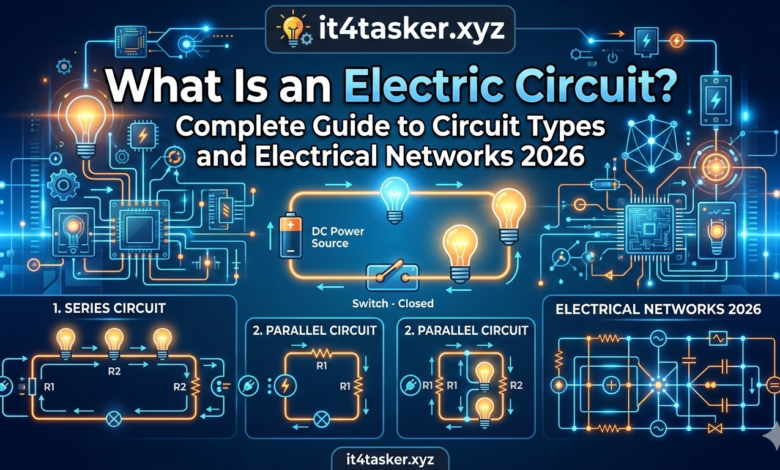
There are three main circuit types: series, parallel, and series-parallel. Each type affects how current flows and how well the circuit works.
- Series Circuits: Components are connected one after another. There’s only one path for current.
- Parallel Circuits: Components are connected between the same two points. This allows for multiple paths for current.
- Series-Parallel Circuits: These mix series and parallel setups. They offer a balance between the two.
How Circuit Type Affects Performance and Efficiency
The circuit type greatly affects its performance and efficiency. For example, series circuits are simple but can fail if one part breaks. Parallel circuits are more reliable because of their redundancy but are more complex to design.
Choosing the right circuit type depends on the application. This includes the needed voltage, current, and power. Understanding these is crucial for creating circuits that meet various electrical system needs.
By picking the best circuit setup, engineers can make electrical networks better. They ensure these networks are reliable, safe, and meet all necessary standards.
Series Circuits: When Components Connect End-to-End
Series circuits are a key setup in electrical engineering. Here, components are linked one after the other. This setup means electric current flows through all components in a single path.
Single Path for Current
In a series circuit, components are connected end-to-end. This lets electric current move through each part in order. Since there’s only one path, the current is the same through each component.
The total resistance in a series circuit is the sum of the individual resistances. Adding more components increases the total resistance. This can impact how well the circuit works.
Advantages of Series Circuit Design
Series circuits are simple and easy to design. They’re perfect for beginners in electronics. They’re also good for situations where a specific total resistance is needed.
Another plus is that they’re easy to fix. Since there’s only one path, finding problems is straightforward.
Key Limitations
Despite their benefits, series circuits have big downsides. One major issue is that if one part fails, the whole circuit stops working. This is a big problem where reliability matters a lot.
Another issue is that the voltage across each part can change. This might not be what you need in all cases.
Everyday Applications in 2026
Series circuits are still used in many ways today. They’re common in simple gadgets like flashlights. Here, they help get the right voltage and current.
In more complex systems, series circuits play a role too. Knowing about series circuits is key for designing and fixing these systems.
Parallel Circuits: Creating Multiple Paths for Current Flow
Parallel circuits are key in modern electrical wiring. They offer reliability and flexibility. Unlike series circuits, where components are connected end-to-end, parallel circuits have multiple paths for current flow. This difference greatly affects the performance, efficiency, and safety of electrical systems.
The Parallel Circuit Configuration Explained
In a parallel circuit, components are connected between the same two points. This allows current to flow through each component in its own path. Each component has its own path, and the voltage across each is the same.
Key characteristics of parallel circuits include:
- The voltage across each component is the same.
- The total current is the sum of the currents through each component.
- The failure of one component does not affect the others.
Why Parallel Circuits Dominate Home and Commercial Wiring
Parallel circuits are widely used in homes and businesses. They provide a consistent voltage to all devices, no matter how many are connected or their resistance.
Benefits of parallel circuits in home and commercial wiring:
| Benefit | Description |
|---|---|
| Reliability | If one device fails, others continue to operate. |
| Flexibility | Devices can be added or removed without affecting the entire circuit. |
| Voltage Consistency | All devices receive the same voltage, regardless of their resistance. |
Potential Drawbacks of Parallel Circuit Design
Parallel circuits have some drawbacks. One major concern is the increased complexity and cost of the additional wiring needed.
Some challenges of parallel circuit design include:
- Increased wiring complexity.
- Higher installation costs.
- Potential for increased total current draw.
Common Uses in Modern Electrical Systems
Parallel circuits are everywhere in modern electrical systems. They are reliable and flexible, making them perfect for many uses.
Examples of parallel circuit applications:
- Household electrical wiring.
- Commercial building electrical systems.
- Automotive electrical systems.
Series-Parallel Circuits: Combining the Best of Both Worlds
Series-parallel circuits mix series and parallel elements in one circuit. This creates a strong and adaptable electrical network. They are vital in many fields because they use the strengths of both series and parallel setups.
Understanding Complex Circuit Configurations
Series-parallel circuits are more complex than simple ones. They have both series and parallel parts. This means we need to understand how current moves and how resistance is figured out.
Key characteristics of series-parallel circuits include:
- Multiple paths for current flow, similar to parallel circuits
- Components connected in series within some branches
- The ability to provide different voltage levels within the same circuit
Calculating Total Resistance and Current in Hybrid Circuits
To analyze a series-parallel circuit, first find the series and parallel parts. Then, calculate the total resistance step by step. This involves combining series and parallel resistances using their formulas.
For example, if two resistors are in parallel and this group is in series with another resistor, do this:
- Find the equivalent resistance of the parallel resistors
- Add this to the series resistor to get the total resistance
Real-World Examples From Automotive to Electronics
Series-parallel circuits are everywhere in today’s tech and electrical systems. In cars, they’re in lighting systems. This way, if one light goes out, others still work.
In gadgets, they help meet specific voltage and current needs. For example, in battery systems, they let us get the most out of voltage and capacity.
Common applications include:
- Automotive electrical systems
- Consumer electronics
- Industrial control systems
- Renewable energy systems
Open, Closed, and Short Circuits: Understanding Circuit States
Knowing the different states of electric circuits is key for designing and fixing electrical systems. There are three main states: open, closed, and short circuit. Each state has its own traits that impact how the circuit works and its safety.
Closed Circuits: The Normal Operating Condition
A closed circuit is when everything is connected right, letting current flow. This is vital for any electrical device or system to work. In a closed circuit, the power source’s voltage pushes current through the parts, making the device work as it should.
Open Circuits: When the Connection Breaks
An open circuit happens when there’s a gap, stopping current flow. This can be from a wire coming loose, a broken part, or a switch turned off. Without a path, electrons can’t move, and no current flows. Open circuits are sometimes on purpose, like when you turn something off, but they can also be due to damage.
Short Circuits: Understanding This Dangerous Condition
A short circuit is a risky situation where electricity finds an easy, unintended path. This leads to a big jump in current, which can cause overheating, damage, or even fires.
What Causes Short Circuits
Short circuits usually come from insulation failure, wire damage, or wrong wiring. When two wires touch that shouldn’t, they make a low-resistance path. This can happen from wear and tear, environmental factors, or mistakes in making the circuit.
The Risks and Consequences of Short Circuits
The dangers of short circuits include fires, damage to electrical gear, and harm to people. They can cause a huge surge in current, leading to overheating and fires. So, it’s important to design circuits with safety features like fuses or circuit breakers to stop the circuit in a short circuit.
Electrical Networks: Beyond Simple Circuits
The world of electrical networks combines circuit theory with real-world use. This mix is key to modern electrical systems. As we move from simple circuits to complex networks, electrical systems get better and more efficient.
Electrical networks link different electrical parts to do specific jobs. They can handle many inputs and outputs. This makes them crucial in today’s tech world.
Distinguishing Networks from Basic Circuits
Basic circuits and electrical networks differ in complexity and what they can do. Simple circuits do one thing, while networks can do many things at once.
Complexity and Scalability are what make electrical networks special. They can grow or change to fit various needs, from small gadgets to big power systems.
Network Topology: Mesh, Star, and Ring Configurations
Network topology is how devices are set up in a network. You’ll find mesh, star, and ring setups, each with its own benefits and drawbacks.
- Mesh Topology: It’s reliable because of its many connections between devices.
- Star Topology: It’s easy to install and maintain, used a lot in home networks.
- Ring Topology: It gives equal access to all devices, often seen in fiber optic networks.
Direct Current Networks and Their Applications
DC networks are used where a steady voltage is needed. You’ll find them in electronic devices, cars, and green energy systems.
Advantages of DC Networks include being easy to understand and store energy in batteries.
Alternating Current Networks in Power Distribution
AC networks are mainly used for power distribution. They’re great for sending power over long distances with little loss.
The efficiency of AC networks in sending power is why they’re used in electrical grids all over the world.
Circuit Analysis Methods Every Beginner Should Know
Understanding circuit analysis is key for anyone working with electrical systems. It involves using various techniques to understand and predict electrical circuit behavior. This knowledge is vital for designing, troubleshooting, and maintaining electrical systems.
Using Ohm’s Law to Calculate Circuit Values
Ohm’s Law is a fundamental principle in circuit analysis. It says the current through a conductor is directly proportional to the voltage and inversely proportional to the resistance. Mathematically, it’s expressed as I = V/R, where I is the current, V is the voltage, and R is the resistance.
With Ohm’s Law, you can find any value if you know the other two. For example, knowing the voltage and resistance lets you calculate the current. This law is essential for understanding circuit operation and making necessary calculations for design.
| Known Values | Unknown Value | Formula |
|---|---|---|
| Voltage (V), Resistance (R) | Current (I) | I = V/R |
| Current (I), Resistance (R) | Voltage (V) | V = I*R |
| Voltage (V), Current (I) | Resistance (R) | R = V/I |
Kirchhoff’s Voltage Law: Conservation of Energy in Circuits
Kirchhoff’s Voltage Law (KVL) states that the sum of all voltages around any closed loop in a circuit must be zero. This law is based on the principle of conservation of energy. It means the total energy gained per unit charge is equal to the total energy lost as you traverse a closed loop.
KVL is expressed as ΣV = 0, where ΣV is the sum of all voltage changes around the loop. This law helps analyze complex circuits with multiple loops and voltage sources.
Kirchhoff’s Current Law: What Goes In Must Come Out
Kirchhoff’s Current Law (KCL) states that the sum of currents entering a node is equal to the sum of currents leaving the node. This law is based on the principle of conservation of charge. It implies that charge cannot accumulate at a node.
KCL is expressed as ΣIin = ΣIout. It’s particularly useful for analyzing circuits at junctions or nodes where multiple branches meet.
Calculating Power Consumption and Efficiency
Power consumption in a circuit is calculated using the formula P = V*I, where P is the power in watts, V is the voltage, and I is the current. Efficiency is a measure of how effectively a circuit converts input power into useful output power. It’s calculated as Efficiency = (Pout/Pin) * 100%.
Understanding power consumption and efficiency is crucial for designing circuits that are not only functional but also energy-efficient and safe.
| Parameter | Formula | Unit |
|---|---|---|
| Power (P) | P = V*I | Watts (W) |
| Efficiency | (Pout/Pin) * 100% | Percentage (%) |
Cutting-Edge Circuit Applications Transforming 2026
Technology is moving fast, and electric circuits are changing our lives in 2026. They are making many things better, like how we live and work. This is thanks to new circuit designs.
Smart Home Circuits and Automated Electrical Systems
Smart homes are everywhere now, thanks to electric circuits. These circuits make it easy to connect smart devices. This makes homes safer, more energy-efficient, and more convenient.
For example, smart lights use low-voltage circuits to save energy. They also let users control lights from anywhere. Also, home security systems depend on complex circuits for reliable monitoring.
Electric Vehicle Charging Infrastructure and Networks
More people are choosing electric vehicles (EVs), which means we need more charging spots. Electric circuits are key to making these charging stations work well.
Fast-charging EVs need special power electronics circuits to charge quickly and safely. Adding renewable energy to EV charging is also becoming common. This makes EVs even better for the environment.
| EV Charging Type | Power Output | Charging Time |
|---|---|---|
| Level 1 | 1.4 kW | 12-24 hours |
| Level 2 | 7.2 kW | 4-8 hours |
| DC Fast Charging | 50 kW | 30 minutes |
Solar and Wind Energy Circuit Integration
Solar and wind power need electric circuits to work well. New circuit tech makes these systems more efficient and reliable.
Solar inverters turn DC power from solar panels into AC power for the grid. Wind turbines use special circuits to make more energy and keep the grid stable.
Internet of Things Devices and Low-Power Circuits
The Internet of Things (IoT) is also changing thanks to electric circuits. IoT devices, like wearables and sensors, use low-power circuits. This helps them last longer on battery.
Creating circuits for IoT devices is all about being efficient with power. Low-power microcontrollers and circuits that harvest energy are key to solving these challenges.
Safety Guidelines and Best Practices for Working With Circuits
Safety is key when working with electric circuits. It affects both people and equipment. Knowing the dangers and following safety rules is crucial.
Identifying and Preventing Common Electrical Hazards
Electrical hazards can cause serious harm, death, and damage to equipment. Risks include electrical shock, fires, and explosions. It’s important to spot these dangers early, during design and installation.
Key hazards to watch out for:
- Insufficient insulation or damaged cables
- Overloaded circuits or improper wiring
- Poor grounding or bonding
- Moisture or water exposure
The National Fire Protection Association (NFPA) says, “Electrical safety is not just about avoiding electrical shock. It’s also about preventing fires and ensuring the overall safety of the electrical system.”
“Electrical safety is a critical aspect of working with electric circuits. It requires a proactive approach to identifying potential hazards and implementing measures to mitigate them.”
— NFPA
Essential Safety Rules for Circuit Design and Installation
Several key rules must be followed for safe circuit design and installation:
- Use appropriate materials and components rated for the specific application.
- Ensure all connections are secure and meet relevant standards.
- Implement proper grounding and bonding techniques.
- Follow local electrical codes and regulations.
| Safety Rule | Description | Benefit |
|---|---|---|
| Material Selection | Choosing components rated for the application | Prevents overheating and component failure |
| Secure Connections | Ensuring all connections are tight and secure | Reduces risk of electrical shock and fires |
| Proper Grounding | Implementing effective grounding and bonding | Protects against electrical shock and equipment damage |
Tools and Techniques for Testing Circuits Safely
Testing circuits is vital for their safety and function. The right tools and methods are key.
Using Multimeters and Voltage Testers
Multimeters and voltage testers are essential for measuring electrical parameters and finding issues. When using these tools:
- Always follow the manufacturer’s instructions.
- Ensure the tool is rated for the voltage being measured.
- Use appropriate personal protective equipment (PPE).
Effective troubleshooting needs a systematic approach. Common problems include short circuits, open circuits, and component failures.
Steps for troubleshooting:
- Identify the symptoms and gather information.
- Isolate the problem area.
- Use appropriate tools to measure and test.
- Apply corrective actions and verify the solution.
By following these guidelines and best practices, individuals working with electric circuits can significantly reduce the risk of accidents and ensure a safe working environment.
Conclusion
Understanding electric circuits is key to using electricity in many ways. This guide has covered the basics of electric circuits, their parts, and how they work.
Important points from this guide include the role of circuit setup. Whether it’s series, parallel, or series-parallel, it affects how well electrical systems work. Knowing about circuit states like open, closed, and short circuits is also vital for safe use.
As technology grows, knowing about electric circuits will keep being important. They play a big part in smart homes, electric cars, and green energy systems. This shows how crucial they are in our daily lives.
By learning about electric circuits, people can better understand their role and uses. This knowledge helps build a strong base for more study and creativity in electrical engineering.
FAQ
What is the most basic way to understand how an electric circuit functions?
An electric circuit is like a race track. Electrons need a complete path to flow and do work. This path goes from a power source, like a Duracell battery, through copper wiring, to a load device, like a Philips LED bulb, and back.If the loop is broken, the flow stops. It’s like the “cars” in the race track can’t move anymore.
Why is Ohm’s Law so important for anyone studying electrical networks?
Ohm’s Law explains how Voltage, Current, and Resistance work together. It shows that Voltage equals Current multiplied by Resistance (V=IR). This helps engineers at Apple or Tesla make sure devices don’t overheat while working well.
What is the difference between a series and a parallel circuit in everyday use?
In a series circuit, components are connected one after another. If one bulb goes out, the whole circuit stops working. On the other hand, parallel circuits have many paths for electricity. This is why your home’s wiring is in parallel.If you turn off your Samsung TV, your Dyson vacuum in another room still works because it has its own path to power.
How do circuit breakers and fuses protect my home from a short circuit?
Circuit breakers and fuses act as safety nets. A short circuit is when electricity takes a shortcut, causing a surge. A Schneider Electric circuit breaker or a fuse detects this surge and cuts off power to prevent fires or overheating.
Can I combine different circuit types into one system?
Yes, you can! These are called series-parallel circuits or hybrid configurations. They’re common in complex electronics, like Dell laptop motherboards or Ford electric vehicle power systems. These setups let designers control voltage and current across different components.
What role does a multimeter play in circuit troubleshooting?
A multimeter, like a Fluke 87V, is key for finding circuit problems. It lets you measure voltage and check wire continuity. It’s the best way to find a bad connection without guessing.
How are renewable energy sources like solar panels integrated into modern circuits?
Modern solar panels use inverters to change Direct Current (DC) to Alternating Current (AC). This AC energy goes into your home’s electrical system. A smart meter tracks how much power you send back to the grid.
What is a “mesh” network topology in the context of electrical systems?
A mesh network is a complex system where every node is connected. It’s used in smart cities and power grids for reliability. If one path fails, power is rerouted through another, keeping services like hospitals running.
.